
CMM Inspection Reports: When Pass or Fail Isn’t the Whole Story
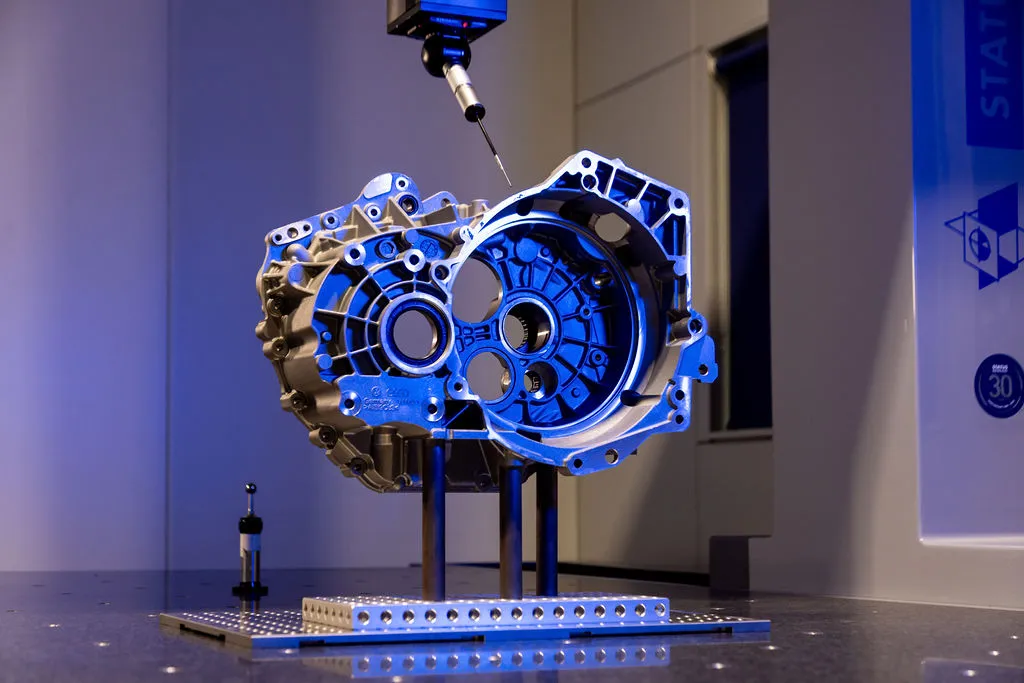
A CMM can measure thousands of points, but the value of the inspection comes down to whether the results answer the question you actually need answering.
Sometimes the job is conformance: does the component meet the specified requirements? In that case, the report needs to make clear what has been evaluated, what the requirement is, what was measured and whether the result is within tolerance.
Other times, the job is investigation. Why won’t two components assemble correctly? Has a component distorted during machining? Where is variation occurring?
In those situations, the value isn’t simply in producing more data. It is in producing the right data, evaluated against the right requirement, so you can understand the problem and decide what to do next.
A result can be completely valid for the characteristic being measured and still leave a wider engineering question unanswered.
A Pass Doesn’t Necessarily Explain the Geometry
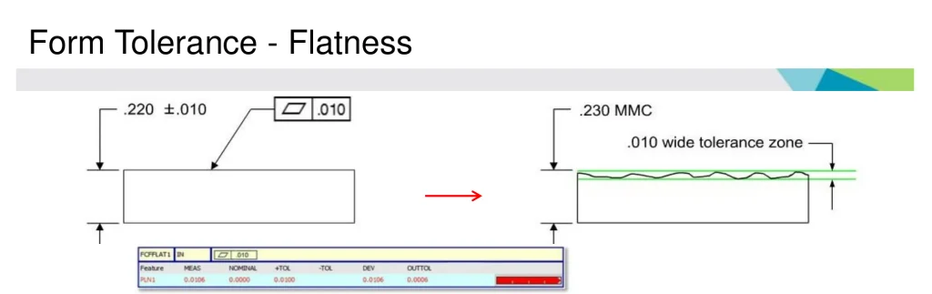
Take a sealing face with a flatness tolerance of 0.100 mm. The CMM measures the surface and reports:
Specified flatness: 0.100 mm
Measured flatness: 0.062 mm
Result: PASS
That establishes something important: the surface conforms to its specified flatness requirement. It does not, however, establish everything about that surface.
Flatness is a form control. It evaluates the surface independently and does not, by itself, control its orientation or location relative to other features.
If that surface needs to mate with another component, other geometric relationships may also be important. Depending on the design intent, those could include parallelism, perpendicularity, position, dimensional separation or profile relative to an appropriate datum reference frame.
A component can conform to an individual drawing requirement and still contribute to an assembly problem elsewhere.
That doesn’t mean changing the requirement or replacing it with something else. The specified requirement remains the requirement. If the inspection is intended to investigate a wider functional problem, that context needs to be understood before deciding what additional measurements or reporting would help.
Where GD&T Comes In
Where components need to mate, align or work together, the relationship between features can be just as important as the individual characteristics being measured.
This is where Geometric Dimensioning and Tolerancing (GD&T) becomes particularly useful. Controls around form, orientation, location and profile can define those relationships and help ensure the inspection reflects how the component is intended to fit and function.
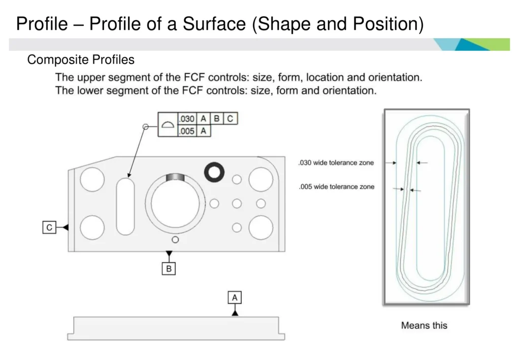
For an investigation, that wider geometric information can help identify whether the issue sits with the characteristic being measured or elsewhere in the relationship between features.
The Result Is Only as Meaningful as the Reference
How the component has been referenced or aligned also matters.
Where a drawing requirement references datums, the relevant feature needs to be evaluated against the appropriate datum reference framework.
A best-fit alignment can be extremely useful for understanding the overall shape of a component or how its geometry varies from nominal, but it does not necessarily demonstrate conformity to a requirement referenced to defined datums.
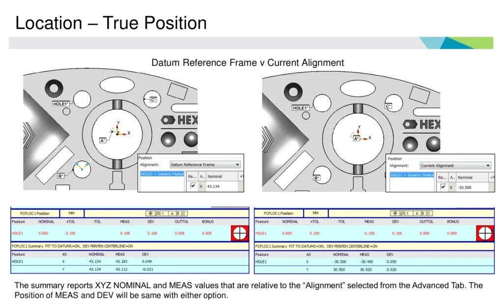
The same measured component can therefore provide different information depending on how the data is evaluated.
What Should a CMM Inspection Report Include?
There is no single reporting format that works for every component, but the basics should be clear.
A useful report will normally identify the component and drawing, the characteristic being inspected, the relevant requirement or nominal value, tolerance, measured result, units and conformity status. Where relevant, it may also need to identify the drawing revision, datum reference frame or alignment used, along with information about the inspection method, conditions or equipment.
The level of detail should reflect the job. A production team checking repeat components may simply need conformity to be obvious, while a quality engineer investigating a manufacturing or assembly problem may need considerably more detail.
More data does not automatically mean a better report.
There may also be cases where the result itself needs more context. For measurements close to a tolerance limit, for example, measurement uncertainty and the applicable decision rule may need to be considered as part of the conformity decision.
When Graphical Reporting Adds Value
A single numerical result can establish conformity but may tell you relatively little about the pattern of variation.
Take a large machined surface. Its flatness result may confirm whether it meets the specified tolerance, but if you are investigating a manufacturing or assembly problem, you may also need to understand how that surface varies. Is one corner high? Has the centre bowed? Is there a trend across the surface?
Graphical reporting can make that variation much easier to understand. Depending on the component, colour maps, point deviation plots, vector displays and cross-sectional information can show patterns that are difficult to see from a single numerical result.
Graphical information still needs context. Alignment, deviation scale and nominal geometry all affect how the report should be interpreted. A colour map covered in dramatic reds and greens may look alarming, but if the scale represents only a few microns, the component could still be comfortably within its specified requirement.
Equally, a visually uneventful graphical report does not override a failed drawing characteristic. Graphical reporting should help explain the measurement data, not replace the engineering requirement the component is being verified against.
Agree the Question Before Measurement Starts
One of the most useful conversations around CMM inspection happens before the component goes anywhere near the machine.
The drawing remains fundamental, but where the inspection is being used to investigate a problem, so does the context around the job. What does the component do? How does it locate? Which features interact with other parts? What problem is being experienced? And ultimately, what decision needs to be made from the results?
Understanding that at the outset helps determine the appropriate measurement strategy and reporting requirements. It can also avoid a component being measured perfectly accurately, only for everyone to realise afterwards that the report does not contain the information they actually needed.
The best time to decide what an inspection report needs to show is before the inspection begins.
At Status Metrology, our subcontract inspection team works with customers to understand not only what needs measuring, but what they need to learn from the results.
If you are unsure how best to inspect a component, what information would be most useful from the resulting report, or whether a wider GD&T issue may be contributing to the problem, get in touch with the Status team.
We also provide GD&T training for teams looking to build confidence around geometric tolerancing and how it applies in practice.
Frequently Asked Questions
Our Proud Partners







 +44 (0) 1159 392 228

